PRACTICAL TIP – Machining of Grooves
May 2021
SYMplus™ offers you many possibilities to effectively implement your work. This also applies to the machining of “Grooves”.
And this is how easy it is:
Open the “Geometry” mode in your SYMplus™ software. Here you first create the contour type “Groove” via F1 “Create” > F1 “User-defined”.
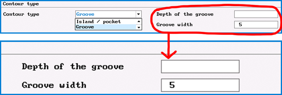
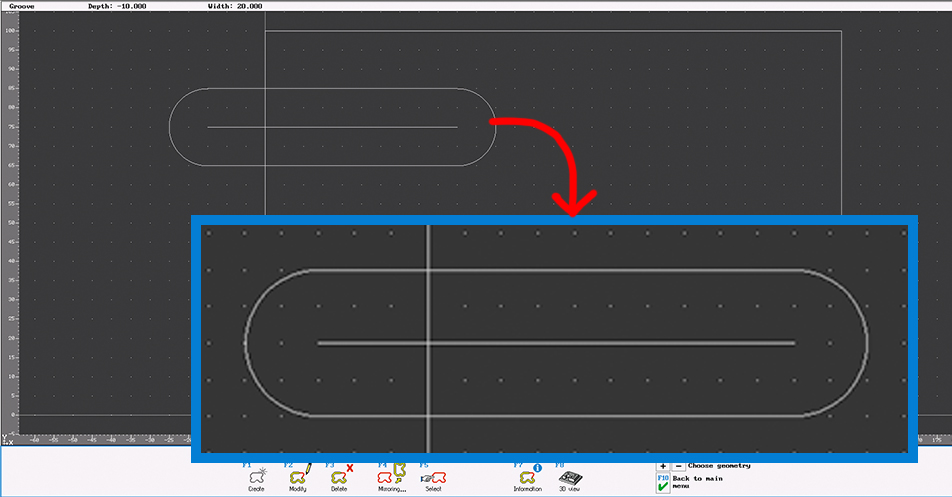
Initially, only the center path of the groove is described there, which in the simplest case is merely a straight line. The outer contour is determined by the groove width, which is entered together with the depth of the groove, right at the beginning of the creation process.
You can also create an open groove. In this case, however, you should make sure that the starting point of the groove is outside the workpiece, as this point is also automatically used as the starting point for the machining operation when machining with the “Groove” step.
Then switch to the “Work plan” mode of operation. There, also select the “Groove” step so that the tool also follows the center path here, as created in the geometry – regardless of whether the tool diameter is smaller than or equal to the groove width.
If you select a small tool, a correspondingly large amount of contour allowance remains.
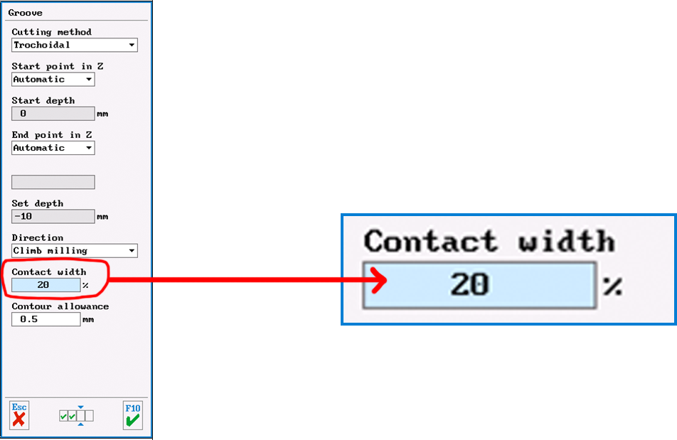
If you have created a groove that is twice as wide as the tool diameter, you can switch the “Cutting method” to “Trochoidal” (whirl milling) on the third dialog page of the “Groove” step. Then – taking into account a contour allowance – the groove is rough-milled over its entire width. When doing this, also make sure to set the “contact width” to a sensible value (e.g. 20%).
However, if you enable an end mill (which usually does not cut across the center) for ” Groove/Engrave” machining, you can also machine an open groove with this tool. Then set the “Infeed type” to “Equal” and the “Infeed point” to “Start”.
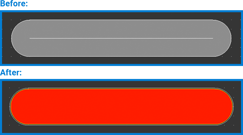
In principle, you can also machine a groove using the “Surface” step. This also applies in particular if the outer contour rather than the center path was designed in the geometry or if only the outer contour of the groove could be transferred from a CAD file. The “Surface” step always works if the tool diameter is smaller than the groove width (if necessary, smaller than the groove width minus 2x contour allowance).
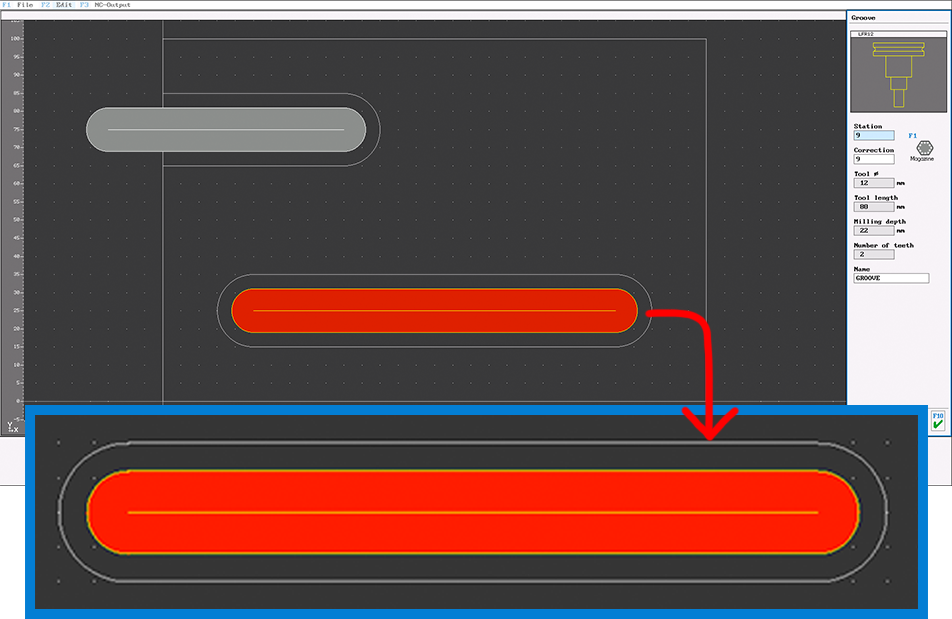
To machine a closed groove with an end mill (without center cut), you can also use the “Surface” step. In this case, however, you must switch the infeed to “Ramp” on the fourth dialog page, because the groove is too narrow for the usually preset helical plunge. Only after this change is the groove recognized as a possible surface to be machined and displayed in red.
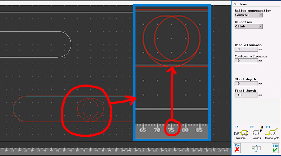
After roughing (work step “Surface”), the edge of the groove can be finished normally like a pocket via the work step “Contour”. Since by default only the transition points between contour elements (i.e. here between the straight lines and the semicircles) can be selected as approach and departure points, the point has been set to the center of the straight line (here X75) via X value on the contour.
Now it is your turn. Try this out by yourself.
You will find more tips in the upcoming newsletters.
You have questions? Contact our experts using the contact form below.
Do you have any questions?
Our experts are at your disposal. We look forward to your inquiry!


