PRACTICAL TIP – Clever Cutting and Reclamping
October 2021
The plan was quite simple.

Cut a turned part to be machined on both sides from the bar and at the same time programme the second machining side. If the length of the blank is defined to such an extent that at the end, there is enough material to “cut” out of the protective zone for the chuck or the clamping jaws.

However, if you proceed as described, after the “cutting off” step it would result in the half-finished workpiece falling in the simulation as in reality the chip tray or a part catcher. Afterwards, the geometry is no longer available in the working plan for further machining.
But what is the solution then? The following practical tip gives you the answer:
Step 1:
Instead of giving the blank an excessive length, make it only slightly longer than the finished part and assign negative values to the outer and inner values of the protection zone (tool width of the parting line).

Step 2:
The half-machined workpiece (red lines) then remains in the routing and can be saved in this form via F1 “File” > F7 “Export” > F1 “Workpiece geometry”.

Step 3:
The new blank can then be used for a second working plan.

Step 4:
Under F4 “Clamping” the workpiece is first turned over. Special attention must then be paid to the input field “Shift Z”. In the example, -0.4 must be entered because, in addition to the stock allowance for the second side of 0.2 mm here, the “slug” left by the cutting radius of the parting-off tool must also be taken into account.
")
Step 5:
The last step is to determine the work steps as usual and as on the first page. Here you benefit from the so-called contour tracking of the software, which recognises where drilling and roughing has already been done from the first page. This becomes visible when creating the work steps by the correspondingly reduced red areas (here for the roughing cut inside).

Now it’s your turn.
Was this tip helpful? Let us know.
You will find more tips in the upcoming newsletters.
You have questions? Contact our experts using the contact form below.
Do you have any questions?
Our experts are at your disposal. We look forward to your inquiry!

This might also be of interest to you
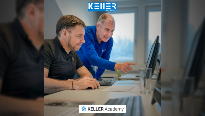
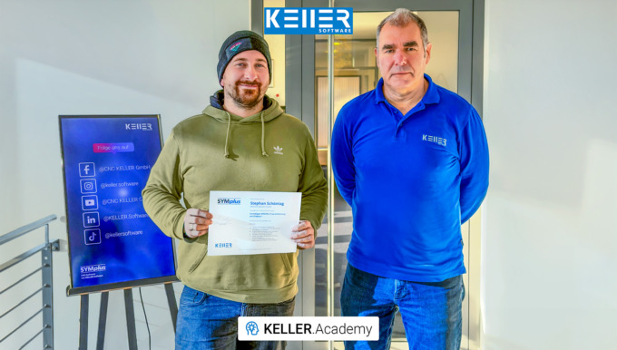
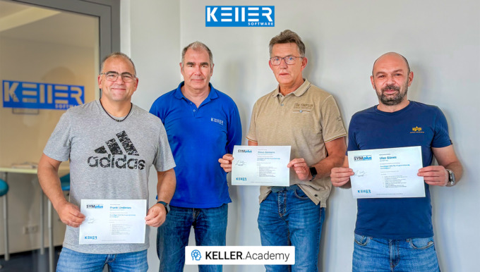
Last week at the KELLER.Academy, participants once again spent their time programming, simulating, and discussing intensively—from the fundamentals of DIN/PAL programming to the practical…
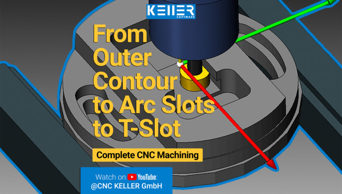
This video demonstrates selected machining steps from Task 13 of the Christiani exercise collection “CNC Milling Technology according to PAL2020”. We illustrate these steps using the 3D simulation…
Operating a CNC Machine using SYMplus™.
How to avoid an idle CNC machine?
Tricky production order and no solution? Schmidt Zerspanungstechnik GmbH had the same problem the other day …
The problem: The control system of their machine does not offer a suitable cycle for two counter-rotating 3-flute flat threads on a spreader roll (Ø152, length approx. 3m).
The solution: A macro in SYMplus™ that can rough and finish the threads with normal grooves in many small infeeds.
Do you have a similar case or something more challenging? Then spare your time and nerves and contact us today using the form below – the KELLER.Software team is ready to help you.

By loading the video you accept YouTube's privacy policy.
Learn more
Do you have any questions?
Our experts are at your disposal. We look forward to your inquiry!
This might also be of interest to you

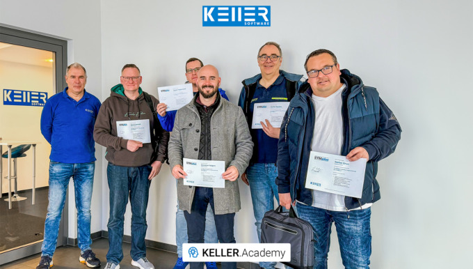
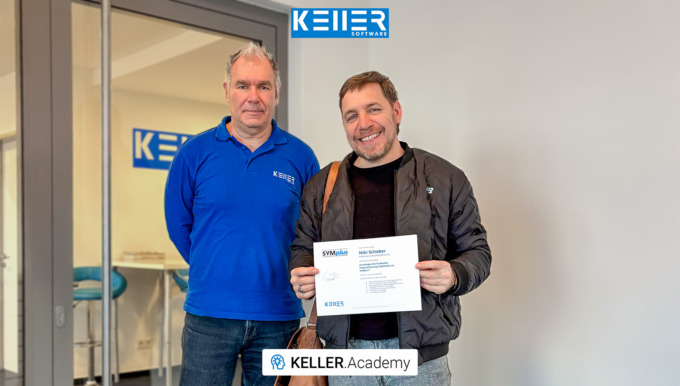
After Mr. Schober had already attended our CAD/CAM course, we were pleased to now welcome Mr. Zaeske from Waldemar Link GmbH & Co. KG. Thank you for your visit, Mr. Zaeske. We wish you every…
After a two-week break (and a successfully completed CAD/CAM course) Mr. Schober from Waldemar Link GmbH & Co. KG returned to the KELLER.Academy for the course “Basic DIN/PAL programming…
Practical Tip: Vocabulary tests? Multiple choice tasks? This is how it works with SYMplus™ – In Video format
If you teach DIN/PAL programming using our SYMplus™ software, you are probably familiar with the “Teacher” mode of operation, which allows you to perform gap-filling tasks in the style of the written IHK(Chamber of Industry and Commerce, Germany) final examinations. What you may not know, however, is that this operating mode gives you many more options than simply using an NC program as a basis.
To learn how to set up vocabulary tests and multiple choice tasks on SYMplus™, watch this video.
To watch more videos like this, please follow our Youtube channel:
https://www.youtube.com/watch?v=D5FngKoU1Qo&t=42s
By loading the video you accept YouTube's privacy policy.
Learn more
For more tips, keep an eye out for our upcoming newsletters.
You have questions? Please feel free to contact our experts using the form below.
Do you have any questions?
Our experts are at your disposal. We look forward to your inquiry!
This might also be of interest to you
In our first course of 2026, the focus for Mr Schober from Waldemar Link GmbH & Co. KG was a hands-on introduction to the CAD/CAM workflow with SYMplus™: How do I build a geometry? Where…

This video demonstrates selected machining steps from Task 10 of the Christiani exercise collection “CNC Milling Technology according to PAL2020”. We illustrate these steps using the 3D simulation…
PRACTICAL TIP – 3 steps to rotary-symmetric contour
July 2021
A pocket or an island contour is usually constructed from the starting point of the contour once around to the end point. In the case of a rotary-symmetrical contour, this would usually be unnecessarily time-consuming and, in part, hardly feasible anyway due to the dimensions.

When programming in SYMplus™, you can achieve the complete contour in just three steps. We will demonstrate it using this drawing:

Step 1:
It is sufficient here to actually construct 1/6 of the contour. We start here on one axis (here it is the negative Y-axis). Since we want to construct 1/6 of 360°, the last element, the circular arc Ø108 must have a run-out angle (to the positive X axis) of 60°.

Step 2:
Now we leave the stretch/arc editor and mirror this piece to the Y axis (or the “X values”). It is important that you select “Mirror and connect”, because otherwise we would have single, “loose” contours.

If you make a mistake when flipping, flip in the wrong direction or forget to connect: With Ctrl+Z you can undo this operation and do it right again.

Step 3:
With this we now have 1/3 of the entire contour and can copy and rotate this section 2x by 120°. Again we select “Copy and Join” and as “Number” the number of copies, namely 2.

Now we have a closed contour, which we can also check again visually in the 3D view:

Now it’s your turn.
You will find more tips in the upcoming newsletters.
You have questions? Contact our experts using the contact form below.
Do you have any questions?
Our experts are at your disposal. We look forward to your inquiry!
This might also be of interest to you
Even trainers sometimes need training themselves. Mr. Schöntag from Motion Makers GmbH has plenty of hands-on experience at the machine, but for his role in vocational training, he wanted to gain…
In this video, we guide you step by step through Task 12 from the Christiani task collection "CNC Turning Technology according to PAL2020". Thanks to our 3D simulation in SYMplus™, everything is…
Simulation of the IHK, German Chamber of Commerce, final examination Milling in Summer 2021(conducted in Germany) for Cutting Machine Operators
By loading the video you accept YouTube's privacy policy.
Learn more
In this simulation, the examination task of the IHK final examination part 2 for cutting machine operators summer 2021 Milling is shown.
Do you have any questions?
Our experts are at your disposal. We look forward to your inquiry!
This might also be of interest to you
Carving pumpkins? 🎃 We’d rather mill ours out of metal. The KELLER.Software team wishes you a Happy Halloween!
In this video, we guide you step by step through Task 12 from the Christiani task collection "CNC Milling Technology according to PAL2020". Thanks to our 3D simulation in SYMplus™, everything is…
Practical Tip: Machining of Grooves – In Video Format
By loading the video you accept YouTube's privacy policy.
Learn more
SYMplus™ offers you many possibilities to effectively implement your work. This also applies to the machining of “Grooves”.
Would you líke to learn how to machine grooves effectively? Watch this video to find out how.
For more tips, keep an eye out for our upcoming newsletters.
You have questions? Please feel free to contact our experts using the form below.
Do you have any questions?
Our experts are at your disposal. We look forward to your inquiry!
This might also be of interest to you
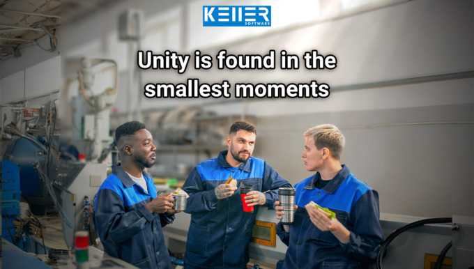
In the CNC world, we speak many languages: Fanuc, Siemens, Heidenhain … But no matter which control system—today, on October 3rd, the Day of German Unity, we celebrate what unites us: our shared…
In this video, we guide you step by step through Task 10 from the Christiani task collection "CNC Turning Technology according to PAL2020". Thanks to our 3D simulation in SYMplus™, everything is…
PRACTICAL TIP – Vocabulary tests? Multiple choice tasks? This is how it works with SYMplus™
June 2021
If you teach DIN/PAL programming using our SYMplus™ software, you are probably familiar with the “Teacher” mode of operation, which allows you to perform gap-filling tasks in the style of the written IHK(The German Chamber of Commerce) final examinations.
But what you may not know yet is that this mode gives you many more possibilities than just using an NC program as a basis.

Reminder: The principle here is that you can define a gap in the NC program for each numerical value, which the students must later determine and enter either exactly or with a certain tolerance. Alternative entries are also possible, for example M13 as an alternative to M3.

Exactly the same principle works with any other text file. No matter whether PAL program or HEIDENHAIN program or something completely different. Because they can all serve as the basis for an exercise or an examination task.
When you realise this, it suddenly opens up a whole lot of new possibilities. So, for example, you can also create text tasks with multiple-choice solutions or calculation tasks (cutting data, production time, etc) with SYMplus™ and evaluate them automatically.
In this picture, for example, you can see a vocabulary test on G and M functions:

In this example, an exact gap is created at the position “G41”. This means that there is only one correct answer.

And in this picture you can see a class assignment with mathematical or text problems:

Here, a range of 456 mm/min to 460 mm/min was defined for the feed rate of the cutter as a response.

Now it is your turn. Try this out by yourself.
You will find more tips in the upcoming newsletters.
You have questions? Contact our experts using the contact form below.
Do you have any questions?
Our experts are at your disposal. We look forward to your inquiry!
This might also be of interest to you
In our course “Basics of DIN/PAL Programming with SYMplus™”, participants spent 1.5 days writing and simulating programs, setting up tools, magazines and turrets, and creating their own gap-filling…
In this video, we guide you step by step through Task 14 from the Christiani task collection "CNC Milling Technology according to PAL2020". Thanks to our 3D simulation in SYMplus™, everything is…
Newsletter May 2021

KELLER.Software Training Initiative
Exam preparations will soon come to an end. This month the IHK(Chamber of Industry and Commerce) final exam part 1 of the cutting machine operators (conducted in Germany) will take place. We wish all trainees the best of luck.
But not only will the exams be over, but also our -now more than one year- running offer “all students get the free student version, no matter if the school/company is a customer of KELLER.Software or not” will end. There have been three final exams during this time and KELLER.Software feels glad to have supported all examinees with this offer. After the current exam this action will expire. This means that from June 1, 2021 all free licenses will be disabled.
Don’t worry though, we have something new for you: The KELLER.Software Training Initiative.

What is the KELLER.Software Training Initiative?
This is a support for all trainees, which makes it possible to book the student version for one year. And it’ even free of charge until 31.12.2021.
For this you only have to fulfill 3 criterias:
- You must be in possession of SYMplus™ with a running plusCARE™ contract.
- You must send us an application with “Expiry date 2021” by e-mail or by form.
- Your students must then re-apply by naming their customer number on the form below. Applications that do not include the customer number or that do not use the form will be ignored.
Re-register via this form > https://cnc-keller.com/buy-symplus/
You are not yet a plusCARE™ customer?
Then contact us now> https://cnc-keller.com/keller-contact/

We have often written that it is our claim to be the best support in your daily CNC everyday life. To ensure that we can continue to live up to this in the future, we have put all our expert knowledge into the new SYMplus™ Update 60, which is now available to all customers with plusCARE™.
This is what’s new as of Update 60> https://cnc-keller.com/symplus-support/new-features-optimizations/
You need help with the Software Update?
Our support will help you > http://cnc-keller.yoursupport.de/cnc.en/search?q=KELLER+update+manager+
We wish you a beautiful day ahead.
– Your KELLER.Software-Team
Practical Tip: Machining of Grooves
SYMplus™ offers you many possibilities to effectively implement your work. This also applies to the machining of “Grooves”.
To learn more about the Tip of the Month, please click on the picture below:
")
Much more from KELLER.Software…

Upcoming Training Sessions:
03.-04. June. 2021: Driven tools, plane swing and reform PAL2020
17.-18. June. 2021:Basics of graphic programming (CAD/CAM) with SYMplus™.
Further Information>https://cnc-keller.com/keller-academy/

Be it a new software update, a new promotion from us or interesting looks behind the scenes of KELLER.Software, if you follow our social media channels, you will always be the first to hear the news.
LinkedIn > Facebook > Instagram > Xing >
To subscribe to our monthly newsletter, please use the form below. Thank you.
Do you have any questions?
Our experts are at your disposal. We look forward to your inquiry!
This might also be of interest to you
In this video, we guide you step by step through Task 9 from the Christiani task collection "CNC Turning Technology according to PAL2020". Thanks to our 3D simulation in SYMplus™, everything is explained…
Work experience instead of making coffee! At KELLER, interns are given real responsibilities from day one. That was also the case for Mr. Born, who – during his two-week internship in application…
PRACTICAL TIP – Machining of Grooves
May 2021
SYMplus™ offers you many possibilities to effectively implement your work. This also applies to the machining of “Grooves”.
And this is how easy it is:
Open the “Geometry” mode in your SYMplus™ software. Here you first create the contour type “Groove” via F1 “Create” > F1 “User-defined”.

Initially, only the center path of the groove is described there, which in the simplest case is merely a straight line. The outer contour is determined by the groove width, which is entered together with the depth of the groove, right at the beginning of the creation process.

You can also create an open groove. In this case, however, you should make sure that the starting point of the groove is outside the workpiece, as this point is also automatically used as the starting point for the machining operation when machining with the “Groove” step.

Then switch to the “Work plan” mode of operation. There, also select the “Groove” step so that the tool also follows the center path here, as created in the geometry – regardless of whether the tool diameter is smaller than or equal to the groove width.

If you select a small tool, a correspondingly large amount of contour allowance remains.

If you have created a groove that is twice as wide as the tool diameter, you can switch the “Cutting method” to “Trochoidal” (whirl milling) on the third dialog page of the “Groove” step. Then – taking into account a contour allowance – the groove is rough-milled over its entire width. When doing this, also make sure to set the “contact width” to a sensible value (e.g. 20%).

However, if you enable an end mill (which usually does not cut across the center) for ” Groove/Engrave” machining, you can also machine an open groove with this tool. Then set the “Infeed type” to “Equal” and the “Infeed point” to “Start”.

In principle, you can also machine a groove using the “Surface” step. This also applies in particular if the outer contour rather than the center path was designed in the geometry or if only the outer contour of the groove could be transferred from a CAD file. The “Surface” step always works if the tool diameter is smaller than the groove width (if necessary, smaller than the groove width minus 2x contour allowance).
To machine a closed groove with an end mill (without center cut), you can also use the “Surface” step. In this case, however, you must switch the infeed to “Ramp” on the fourth dialog page, because the groove is too narrow for the usually preset helical plunge. Only after this change is the groove recognized as a possible surface to be machined and displayed in red.

After roughing (work step “Surface”), the edge of the groove can be finished normally like a pocket via the work step “Contour”. Since by default only the transition points between contour elements (i.e. here between the straight lines and the semicircles) can be selected as approach and departure points, the point has been set to the center of the straight line (here X75) via X value on the contour.

Now it is your turn. Try this out by yourself.
You will find more tips in the upcoming newsletters.
You have questions? Contact our experts using the contact form below.
Do you have any questions?
Our experts are at your disposal. We look forward to your inquiry!
This might also be of interest to you
In our 1.5-day KELLER.Academy course, Mr. Ambrosy from Mager GmbH (a manufacturer of screws and turned parts) successfully completed the introduction to graphical programming with SYMplus™. The…
In this video, we guide you step by step through Task 9 from the Christiani task collection "CNC Milling Technology according to PAL2020". Thanks to our 3D simulation in SYMplus™, everything is explained…
SYMplus™ Update 60
With lots of brand new features and improvements, SYMplus™ Update 60 is available for all our customers with plusCARE™.

Would you like to know what improvements have been carried out? Here is the link for you: https://cnc-keller.com/symplus-support/new-features-optimizations/
You dont have plusCARE™ yet or do not know what plusCARE™ is and its advantages are? Head to our website to find it out and contact us:
Do you have any questions?
Our experts are at your disposal. We look forward to your inquiry!
This might also be of interest to you
In this video, we guide you step by step through Task 11 from the Christiani task collection "CNC Turning Technology according to PAL2020". Thanks to our 3D simulation in SYMplus™, everything is…

In this video, we guide you step by step through Task 8 from the Christiani task collection "CNC Turning Technology according to PAL2020". Thanks to our 3D simulation in SYMplus™, everything is explained…