Happy Easter
KELLER.Software wishes you a Happy Easter and Sunny Spring days ahead!
Do you have any questions?
Our experts are at your disposal. We look forward to your inquiry!
This might also be of interest to you
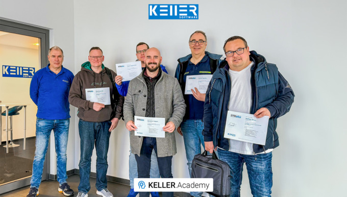
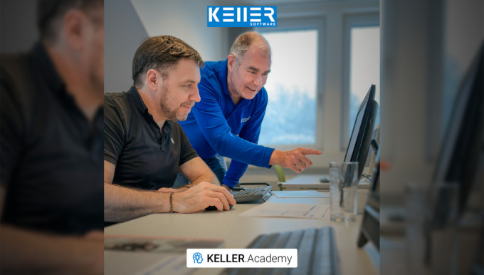
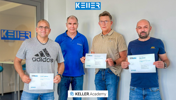
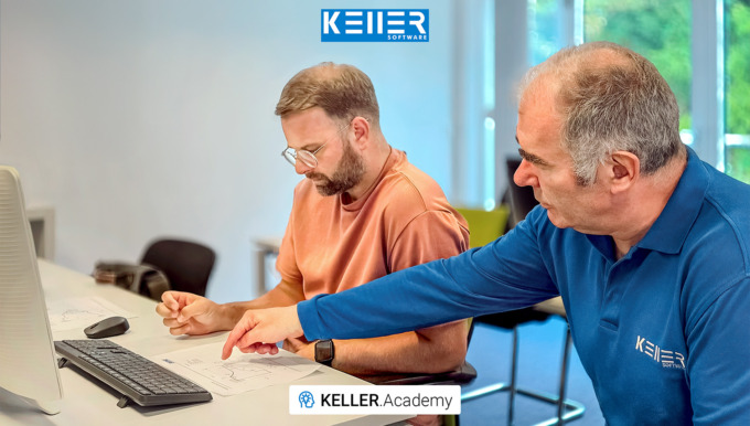
Last week at the KELLER.Academy, participants once again spent their time programming, simulating, and discussing intensively—from the fundamentals of DIN/PAL programming to the practical…
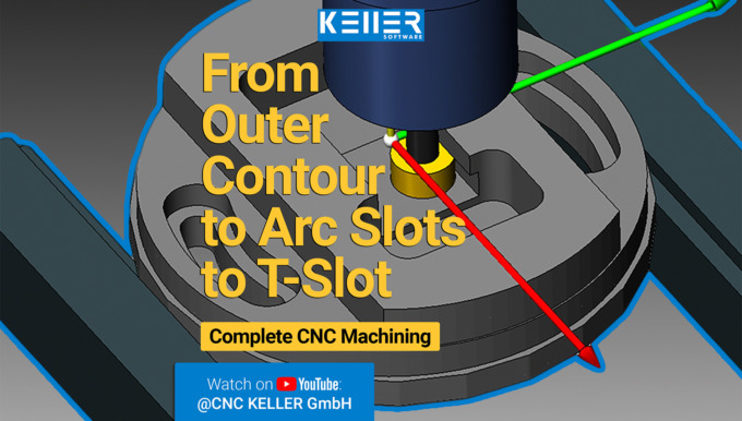
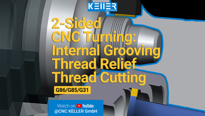
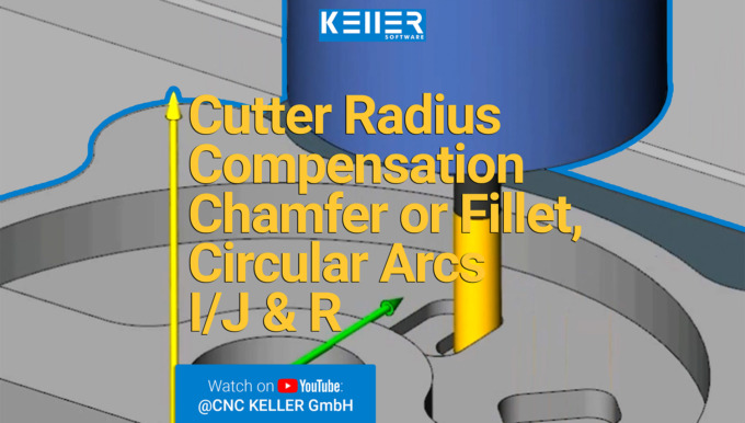
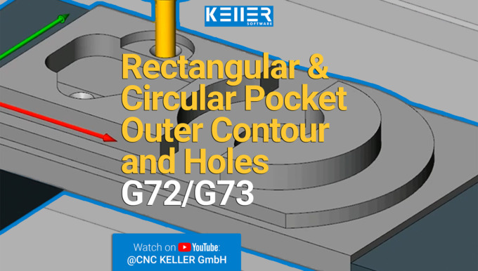
This video demonstrates selected machining steps from Task 13 of the Christiani exercise collection “CNC Milling Technology according to PAL2020”. We illustrate these steps using the 3D simulation…
SYMplus™ Update 62
SYMplus™ Update 62 is now available to all customers with plusCARE™ and includes new features as well as great improvements.

Would you like to know what is new in this update? You can find out via this link: https://cnc-keller.com/symplus-support/new-features-optimizations/
Don’t have plusCARE™ yet? Visit the link below to find out all the information and advantages of it. Contact us and become a plusCARE™ customer to stay up to date.
https://cnc-keller.com/symplus-support/pluscare/
Do you have any questions?
Our experts are at your disposal. We look forward to your inquiry!
This might also be of interest to you

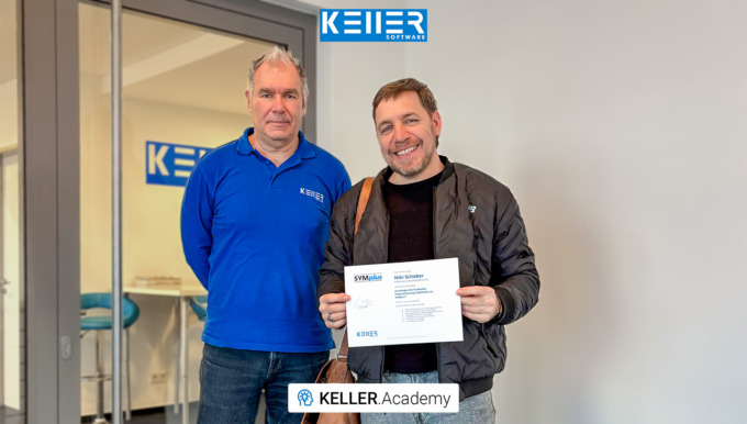
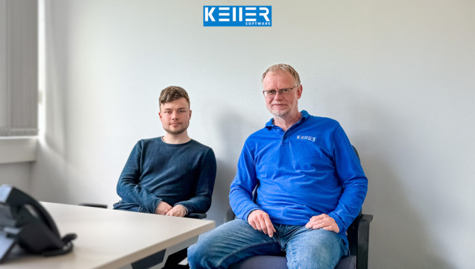
After Mr. Schober had already attended our CAD/CAM course, we were pleased to now welcome Mr. Zaeske from Waldemar Link GmbH & Co. KG. Thank you for your visit, Mr. Zaeske. We wish you every…
After a two-week break (and a successfully completed CAD/CAM course) Mr. Schober from Waldemar Link GmbH & Co. KG returned to the KELLER.Academy for the course “Basic DIN/PAL programming…
Newsletter March 2022

Innovations and the future of learning.
We have good news: The next SYMplus™ update will be available in the next few weeks for all customers with a plusCARE™ contract.

You can expect improvements to PAL2020, optimisations to the software performance and much more in Update 62 of your SYMplus™ CNC software. As soon as it is online, we will let you know immediately. Please keep an eye on our social media channels (Facebook, Instagram, LinkedIn), our website or the update notification in the software.
In this context, we would also like to point out that Update 61 was already available last week. However, this had a bug and so we reacted quickly and stopped it without further ado. Therefore, you don’t need to worry about this. With Update 62, this error has been fixed.
All new features and optimisations can always be found here on our website.

The Bett UK Education Exhibition is taking place in London this month (23 – 25 March). Mr. Reckermann, our head of sales and KELLER software expert, will be there to discuss with educators from all over the world how learning can be shaped in the future – and, of course, what KELLER.Software can contribute to it. We are already looking forward to these inspiring days and will report on our impressions from London in the next newsletter.
You can find more information about the fair here on our website.
Much more from KELLER.Software…
")
Next appointment:
21.-22. April 2022: Exam preparation PAL
More info > https://cnc-keller.com/keller-academy/

The practical tips from the monthly KELLER newsletter are also available in video form. Watch it at any time and free of charge on the KELLER.Software YouTube channel >
https://www.youtube.com/playlist?list=PLo0O792GpB41B8gt89rFWHJ6BFQWvB2wK
To subscribe to our monthly newsletter, please use the form below. Thank you.
Do you have any questions?
Our experts are at your disposal. We look forward to your inquiry!
This might also be of interest to you
In our first course of 2026, the focus for Mr Schober from Waldemar Link GmbH & Co. KG was a hands-on introduction to the CAD/CAM workflow with SYMplus™: How do I build a geometry? Where…

This video demonstrates selected machining steps from Task 10 of the Christiani exercise collection “CNC Milling Technology according to PAL2020”. We illustrate these steps using the 3D simulation…
Newsletter February 2022
Learn new things faster and more effectively

It is no secret that learning is increasingly taking place on the Internet.
Videos are particularly popular. Videos increase the clarity of a topic through their visual presentation and, because our brains remember images better than texts, help us retain information in our heads for longer.
That’s why we at KELLER.Software have been running a YouTube channel for a few years now, covering topics such as:
How does the machining of Grooves work?> https://www.youtube.com/watch?v=SqqflAwVSeE
How to setup vocabulary tests and multiple choice tasks using SYMplus™ software?> https://www.youtube.com/watch?v=D5FngKoU1Qo&t=4s
How to compare production strategies effortlessly with each other using SYMplus™ software?> https://www.youtube.com/watch?v=wSeaABYL7wg&t=3s
There is something for everyone. No matter whether you are just taking your first steps as an apprentice or would like to further your education as an experienced person.
Click here to go to the KELLER.Software YouTube channel > https://www.youtube.com/c/CNCKELLERGmbH
Practical Tip: From PAL Programming to chips

The phrase “From PAL programming to chips” refers to the fact that with SYMplus™ you can not only learn the theory, but you can also build a bridge to practical application.
To learn more about this Tip of the Month, please click on the picture.
Much more from KELLER.Software…
")
Upcoming Training Sessions:
10.-11. Mar. 2022: Driven tools, plane swing and reform PAL2020
17.-18. Mar. 2022: Basics of graphic programming (CAD/CAM) with SYMplus™.
Further Information> https://cnc-keller.com/keller-academy/
To subscribe to our monthly newsletter, please use the form below. Thank you.
Do you have any questions?
Our experts are at your disposal. We look forward to your inquiry!
This might also be of interest to you
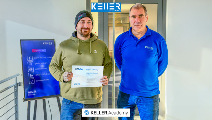
Even trainers sometimes need training themselves. Mr. Schöntag from Motion Makers GmbH has plenty of hands-on experience at the machine, but for his role in vocational training, he wanted to gain…
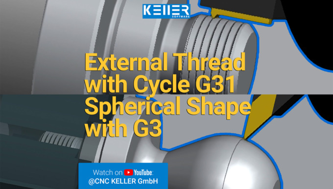
In this video, we guide you step by step through Task 12 from the Christiani task collection "CNC Turning Technology according to PAL2020". Thanks to our 3D simulation in SYMplus™, everything is…
PRACTICAL TIP – From PAL Programming to chips
February 2022
The phrase “From PAL programming to chips” refers to the fact that with SYMplus™ you can not only learn the theory, but you can also build a bridge to practical application. Please note that whether you have a new machine with SIEMENS, HEIDENHAIN or HAAS or one from the 80s with a Dialog 4, EPL or CNC432 control, it always works the same way.
We will show you in the following practical tip how this works:
Step 1
Load the program you want to put on the machine into the PAL simulator and test it diligently using the simulation.

Step 2
Now carry out the following steps 1, 2 and 3:

Step 3
Generate NC program:

3.1.
Search for the parameter file of the desired control via F1 “Control parameters” and confirm the selection with F10.
3.2.
Use F2 “Folder” to select the location where you want to save the program ( for example, this could be on a hard disk or a USB stick)
3.3.
Please be aware that older controllers in particular only allow numbers and no letters in the “Name” field. Also, please refrain from using special characters and spaces.

Step 4
The program must now be transferred to the machine. This can be done either via network, USB connection or “serially” using the “Transfer” mode of SYMplus™.

Step 5
Test the generated program again using the simulation graphic on the control. If any changes are necessary, feel free to contact us.
Step 6
When everything is running smoothly: Why not record your success with a photo or video and send it to us? We are always happy to receive such responses. We look forward to seeing your PAL programming practice workpieces on the machine!
Was this tip helpful? Let us know.
You will find more tips in the upcoming newsletters.
You have questions? Contact our experts using the contact form below.
Do you have any questions?
Our experts are at your disposal. We look forward to your inquiry!
This might also be of interest to you
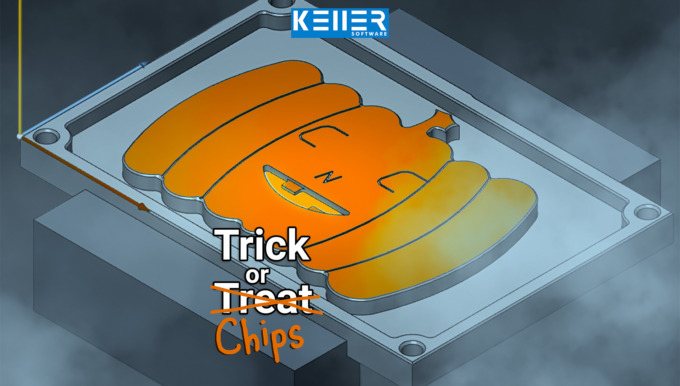
Carving pumpkins? 🎃 We’d rather mill ours out of metal. The KELLER.Software team wishes you a Happy Halloween!
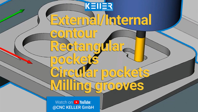
In this video, we guide you step by step through Task 12 from the Christiani task collection "CNC Milling Technology according to PAL2020". Thanks to our 3D simulation in SYMplus™, everything is…
Newsletter January 2022
Into the new year with good news.
KELLER.Software wishes you a Happy and Prosperous New Year 2022.

We at KELLER.Software, are also back from a week of company holidays, refreshed, relaxed and energized. We usually like to start our new year with good news. 2022 is also not different. The good news this year is that the free PAL student licenses that we offered to support students during the pandemic, to help them train from home, has been extended till 30.06.2022. Please note that you can only apply for these free licenses until 30.05.2022. We hope this small gesture from us helps support your students in their training.
In case you are a student/trainee in Germany and you haven’t applied for it yet, feel free to do it here > https://cnc-keller.de/symplus-erwerben/#simplus-fuer-zuhause
")
You probably already read on our social media channels that we are participating in the education exhibition in London, BETT UK 2022. Please note that the exhibition dates have been postponed from January to March 23 – 25, 2022 due to the current restrictions in London from the pandemic. Of course, this does not diminish our excitement. We are very much looking forward to spending three days immersed in inspiring content, networking and exchanging ideas with educators from all over the world.
More info on this can be found here: https://cnc-keller.com/aktuelles/bett-uk-2022-education-exhibition/
Once again KELLER.Software wishes you a successful 2022.
Much more from KELLER.Software…
Next appointments:
10.-11. Feb. 2022: Basics of graphical programming (CAD/CAM) with SYMplus™
24.-25. Feb. 2022: Basic DIN/PAL programming with SYMplus™
More info > https://cnc-keller.com/keller-academy/

Let us learn something new this new year. Head over to the KELLER.Software YouTube channel where you can learn all about SYMplus™ and watch other interesting CNC videos as well.
Stop by and leave a subscription to never miss any new videos > https://www.youtube.com/c/CNCKELLERGmbH
To subscribe to our monthly newsletter, please use the form below. Thank you.
Do you have any questions?
Our experts are at your disposal. We look forward to your inquiry!
This might also be of interest to you
In the CNC world, we speak many languages: Fanuc, Siemens, Heidenhain … But no matter which control system—today, on October 3rd, the Day of German Unity, we celebrate what unites us: our shared…
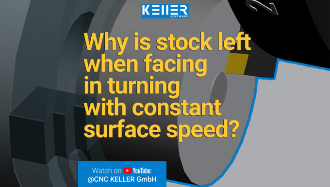
In this video, we guide you step by step through Task 10 from the Christiani task collection "CNC Turning Technology according to PAL2020". Thanks to our 3D simulation in SYMplus™, everything is…
Newsletter December 2021
Your 2021 with KELLER.Software.
The year 2021 was once again full of challenges, experiences and innovations. But before we wish each other “Merry Christmas and a good and successful year 2022”, December once again offers the opportunity to look back together into the last year:


And in December? The KELLER.Software team will be there for you as usual, so that you can get everything sorted before the end of the year.
Much more from KELLER.Software…


For more Information > https://www.mib-airserver.de

Next appointments:
In 2022, the doors of the KELLER.Academy will remain open for you. Keep an eye on our website for new schedules or contact us to book your next training.
More info > https://cnc-keller.com/keller-academy/
To subscribe to our monthly newsletter, please use the form below. Thank you.
Do you have any questions?
Our experts are at your disposal. We look forward to your inquiry!
This might also be of interest to you
In our course “Basics of DIN/PAL Programming with SYMplus™”, participants spent 1.5 days writing and simulating programs, setting up tools, magazines and turrets, and creating their own gap-filling…
In this video, we guide you step by step through Task 14 from the Christiani task collection "CNC Milling Technology according to PAL2020". Thanks to our 3D simulation in SYMplus™, everything is…
Practical Tip: 3 steps to rotary-symmetric contour – In Video format

By loading the video you accept YouTube's privacy policy.
Learn more
A pocket or an island contour is usually constructed from the starting point of the contour once around to the end point. In the case of a rotary-symmetrical contour, this would usually be unnecessarily time-consuming and, in part, hardly feasible anyway due to the dimensions. When programming in SYMplus™, you can achieve the complete contour in just three steps. Watch the video to find out how.
Please follow our Youtube channel to watch the latest videos:
https://www.youtube.com/channel/UCyBovavGxzuJmrm1OXZuErw
For more tips, keep an eye out for our upcoming newsletters.
You have questions? Please feel free to contact our experts using the form below.
Do you have any questions?
Our experts are at your disposal. We look forward to your inquiry!
This might also be of interest to you
In this video, we guide you step by step through Task 9 from the Christiani task collection "CNC Turning Technology according to PAL2020". Thanks to our 3D simulation in SYMplus™, everything is explained…
Work experience instead of making coffee! At KELLER, interns are given real responsibilities from day one. That was also the case for Mr. Born, who – during his two-week internship in application…
Customer Review KNIPEX (Part 2)
Knipex has been using SYMplus CNC software for more than 15 years now in their training. In this video, hear directly from the Head of Technical Training at Knipex, Mr.Herkert, what makes KELLER their preferred CNC Software in training.
By loading the video you accept YouTube's privacy policy.
Learn more
Do you have any questions?
Our experts are at your disposal. We look forward to your inquiry!
This might also be of interest to you
In our 1.5-day KELLER.Academy course, Mr. Ambrosy from Mager GmbH (a manufacturer of screws and turned parts) successfully completed the introduction to graphical programming with SYMplus™. The…
In this video, we guide you step by step through Task 9 from the Christiani task collection "CNC Milling Technology according to PAL2020". Thanks to our 3D simulation in SYMplus™, everything is explained…
Customer review KNIPEX (Part 1)
Training more than 70 apprentices with different levels of knowledge is a big task.
Hear from Mr.Herkert, the head of technical training at the firm Knipex as he explains how KELLER has helped him through this challenge for many years as well as in times of Homeschooling since 2020.
By loading the video you accept YouTube's privacy policy.
Learn more
Do you have any questions?
Our experts are at your disposal. We look forward to your inquiry!
This might also be of interest to you
In this video, we guide you step by step through Task 11 from the Christiani task collection "CNC Turning Technology according to PAL2020". Thanks to our 3D simulation in SYMplus™, everything is…
In this video, we guide you step by step through Task 8 from the Christiani task collection "CNC Turning Technology according to PAL2020". Thanks to our 3D simulation in SYMplus™, everything is explained…